Replacing Electrolytic Capacitors
The best way to learn how to recap is to try doing it yourself. For less than the cost of a movie and popcorn for two you can purchase a dead set and the necessary tools and supplies.
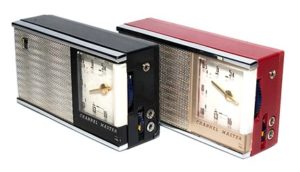 We’ll be using the same radio for signal tracing and alignment examples, so purchasing a dead or dying Channel Master 6056 or RCA Victor P-332 radio will give you a great way to follow along. (The RCA Victor unit was made by Channel Master and identical.)
You can work along if you have a Channel Master 6506 like the one used in this lesson. The same model will be used for the signal tracing and alignment sections of the site. eBay usually has them for under $25.00
Recap Kits
You can find complete electrolytic capacitor replacement kits containing specific components and instructions for many popular American and Japanese portable transistor radios, along with other related items for collectors HERE. There is a kit for the Channel Master radio used in this example.
You Can Do This!
You can replace electrolytics, even if you have never done any service work before. The necessary skills can be acquired in less than an hour. You will need to know how to:
- Open radios without damaging them;
- Remove printed circuit boards;
- Identify the electrolytic capacitors in the radio;
- Remove the old components by desoldering them;
- Replace the capacitors by soldering them in the correct; locations while observing their polarity;
- Test and then reassemble the radio.
If you are don't know how to recognize electrolytic capacitors start here. You are familiar with the concept of component polarity and how to spot positive and negative leads on both old and new electrolytics.
Typical AM-only pocket radios have between two and seven axial and/or radial electrolytic capacitors, with an average about four.
Remove & Replace Parts
A Printed Circuit Board (PCB) is a thin, non-conducting substrate coated with gold or other conductive metal foil. The foil is etched to create conductors, which act like wires, interconnecting the components.
The component wires from transistors, capacitors and other parts are stuck through holes in the PCB’s foil. Then they are soldered into place. Soldering creates both a mechanical and electrical bond.
You must unsolder the correct parts without damaging the circuit board or surrounding components. This can be frustrating, on smaller sets.

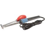
Solder sucking and wicking tools can help you remove the excess solder from joints. They come in all sizes and shapes. I prefer using a solder sucker like the one shown here rather than braided wick shown above it. With a sucker you will be much less likely to damage the radio, and not need three hands.
General Tips and Cautions
- Do recap work when you are fresh and attentive. Quit when you become tired or distracted.
- Be very careful using soldering and desoldering tools around plastic radio cases.
- Too much heat can damage the board and/or the component. Too little heat can cause a faulty, or so-called cold solder joint.
Desoldering Tips and Cautions
- Removing capacitors is trickier than installing them, and you can easily ruin a radio if you are not careful. Practice on a junker.
- Mark polarities on the board as you remove capacitors.
- Make sure you are working on the right joint! ‘Sounds obvious, but it’s easy to get confused.
- Gently wiggle and pull the capacitor from the component side as you heat the joint.
- Too much heat will damage the foil. Take “cooling” breaks when you encounter stubborn joints.
- Avoid “splattering” solder on the board. If this happens, clean it up immediately.
- If using desoldering wick, cut off the end when it gets clogged.
- The braid gets hot. Watch your fingers, especially as the braid gets shorter.
- Pull the braid away from the circuit board before cooling it. Otherwise you’ll pull you’ll pull up part of the copper trace.
- Use a magnifying glass, especially on small sets to be sure you have cleaned up all the splatters.
- Read more HERE.
Try One: Recapping a Channel Master 6506
Lets use a Chanel Master 6056 or RCA Victor P-332 like the ones shown above. These are fairly easy to find on eBay. You can usually buy one for under $25.00. They are well-built, and impressive performers when restored.Let’s use an affordable, readily available Channel Master 6506 similar to the ones shown in Figure 137 for the Recap exercise; and for the Signal Tracing and Alignment projects that will follow.
You will find this model challenging enough to tackle with satisfaction. Channel Master 6506 radios are also big enough so that you won’t need a microscope or tweezers. They are rugged, and will endure many beginner’s mistakes. Purchase one that is already cosmetically correct, or that will clean up easily using the techniques in this book.
Opening the 6502
- Place the set face-down on a towel or other soft, clean work surface to prevent damage to the radio’s face.
- Unscrew the large screw and set aside the radio’s back.
- Unsnap and set aside the six-volt battery holder.
- Remove the metal center post from the PCB using a flat blade screwdriver to loosen it.

Unscrew the post. - Remove and save the two silver flathead screws holding the PCB. Do not unscrew any brass screws yet.
- Carefully clip the wire shown below. It connects the PCB to the small antenna jack. Clip it at the jack end of the wire. Save the orange “spaghetti” insulation that will slide off of the cut wire.
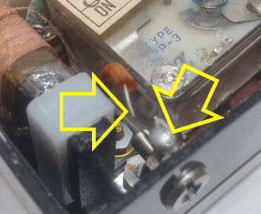
Clip the wire. Save the insulation. - Remove and save the cardboard spacers at the antenna ends.
- Work slowly now. While using care to avoid damaging the fragile antenna, gently slide PCB up and to the right until it clears the case. Wiggle the PCB gently if necessary.
- Fold the radio back to gain access to the underside of the PCB. Don’t break the speaker or earphone wire connections. Use care to not damage the tuning pointer or dial face.
Carefully remove the board from the case. - Gently pry off the dial pointer without bending it.

- Remove the two sets of brass screws, washers and nuts that hold the white dial plastic dial plate to the PCB. You will need to gently flip the PCB to reach one of the screw heads. A small nut driver will help. Set aside the screws, nuts and dial plate.
- Do NOT try to pry off the blue tuning knob. Instead, use needle nose pliers to carefully unscrew and remove the brass nut that holds the knob in place as shown here. Set parts aside.
Unscrew the dial nut.
Replacing the Capacitors
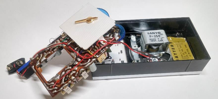
You will be replacing seven (7) electrolytic capacitors. Six of the are radials. One is an axial device.
Because 30μF capacitors are virtually impossible to purchase, you will probably need to replace them with 33μF caps. The 5μF device will likely need to be replaced with a 4.7μF unit. This is perfectly fine.
| ID | Original | New | Style | General Location |
| C1 | 30μF | 33μF | Radial | Between IF and audio transformers |
| C2 | 30μF | 33μF | Radial | Near battery holder |
| C3 | 30μF | 33μF | Radial | Other side of screw post from C4 |
| C4 | 30μF | 33μF | Radial | Closest to screw post |
| C5 | 30μF | 33μF | Radial | Near volume control and tuning cap |
| C6 | 5μF | 4.7μF | Axial | Axial near speaker opening |
| C7 | 30μF | 33μF | Radial | Between Antenna and speaker |
Removing and Replacing Capacitors

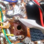
As you can see above, this radio has numerous wires on the underside of the PCB. You need to work very carefully to avoid melting the insulation on the wires. Gently bend or hold wires away from areas whenever you use soldering or desoldering tools.
You will likely need to temporarily unsolder the brown wire shown in the photo and move it out of the way. The photo above shows the locations, part numbers, and polarities of the pads needing to be desoldered.
NOTE: The pointers in the callouts show the locations of the negative PCB holes. Place the new cap minus leads in these holes.
Don’t forget to reattach the brown wire when you are done recapping.
Reposition any wires you have moved out of the way. Make sure they won’t be crimped by the case when you reinstall the PCB.
Reattach the antenna wire to the antenna jack. Use the insulation spaghetti you saved earlier.
More Recapping Tips
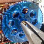
 I like to use the dental tool shown on the right to fully open up the holes after removing the old capacitors. This makes it easier to insert the replacement capacitors.
- Reverse the assembly steps taking care to not break or pinch wires.
- Squirt contact cleaner on the volume control while the circuit board is out of the case.
- Look for other damage and clean battery contacts while the set is apart.
- Carefully clean any clear dial plastic and other visible parts while the radio is apart. Use a soft cloth. This plastic scratches easily.
What Do You Think?
Have you used one of my recap kits? What models would you like to see next? Do you have tips and experiences to share? Questions? Suggested corrections or additions? Leave a comment below. I’ll review comments and post or incorporate the most useful ones. Your email address is required if you choose to comment, but it will not be shared.
I’ve just obtained a Hallicrafters S-120A and wondering if you have a cap kit? It has a hum even on standby. Does this sound like caps?
Sorry,
‘Only selling recap kits for solid state devices for the foreseeable future. https://www.tubesandmore.com/ is a great source for high voltage caps.
There are plenty of online places to download PDFs of service docs for that great little radio.
Best of luck with your restoration!
Ron
Randy – Go to Hayseed Hamfest LLC online and I’m sure they will have a complete kit for the s-120A.
I have a philco transistor radio model T90 and i changed the tuning capicator and now the dial is backwards ?
What can i do to correct it