Capacitors, Electrolytic
Electrolytic capacitors perform a number of important roles. And unlike transistors, they don’t always age gracefully.
Defective electrolytics can be responsible for dead radios, distorted sound, short battery life, and more. Electrolytic capacitors perform a number of important roles. And, unlike transistors, they don’t always age gracefully.

Here's how electrolytic capacitors look on schematics. A variety of symbols have been used over the years.
Notice the plus and minus signs. Correct polarity is critical when replacing electrolytics.
Identifying Polarity
Older capacitors have black dots identifying negative leads. Some have red ends for positive leads. New caps have crimped case ends or long wires for positive leads.
Electrolytic Capacitor Units of Measure
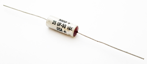
Electrolytic capacitor values are rated in microfarads (Abbreviated as μF, or mF or mFd). They are marked with maximum operating voltages, which are typically greater than the radios’ battery voltage. You must consider an electrolytic’s size, shape, value, rated operating voltage, and lead polarity when replacing it.
Axial vs. Radial Electrolytics
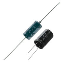
Early radios all used electrolytic capacitors with leads coming out of each end. This configuration is called Axial. As radios became smaller and smaller all components were redesigned to take up less space.
A big reason that radios could fit into pockets was the development of electrolytic capacitors with both leads coming out of the bottom of the devices. These are called Radial capacitors. The photo shows an example of both configurations. The radial cap is on the bottom and the axial is on the top.
Multi-value Electrolytics
 Some capacitors cases hold more than one capacitor. For instance, there might be a three-section cap with a 10, 20 and 100μF all in one cylinder. Exact replacements for these multi-section caps are almost impossible to find.
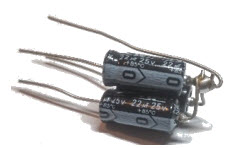
It’s easy to make your own radial multi-caps by connecting multiple axial caps together as seen here. Be sure to get the polarity right before soldering everything together!
Preserving Vintage Cap Appearance
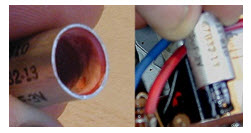
Today’s capacitors don’t look as nice as the vintage ones, which were typically enclosed in aluminum or plastic. Replacing these with contemporary ones makes the radio look – well, restored.
One way around this is to hollow-out the old cap case and covering the new ones with it. Use a drop of epoxy to secure the shell. There is no going back once you do this, so think twice before boring out vintage collectible electrolytic capacitors. Also, be sure that the new caps will actually fit inside the shell of the old ones before proceeding.
What Do You Think?
Do you have tips and experiences to share? Questions? Suggested corrections or additions? Leave a comment below. I’ll review comments and post or incorporate the most useful ones. Your email address is required if you choose to comment, but it will not be shared.
Be the first to comment