Why Trace?
A signal tracer is simply an amplifier that can detect audio and RF signals and then play them through its built-in speaker. By tracing signals stage-by-stage through your radio you can find the issues that cause it to not play or play poorly. When you know which parts of the radio are working properly you can concentrate on suspect stages and components.
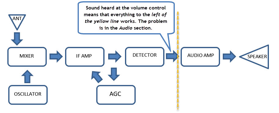
For example, if you can hear a local radio station through a signal tracer connected to the center tap on the volume control, but there is no sound from the radio's speaker you know that the antenna, tuning circuits, IF section and detector are all working. You can then concentrate on the audio circuitry, speaker and earphone jack.
As you will see, in a working radio, you should be able to trace "forward" through the set with the signal tracer and hear the radio station at the inputs and outputs of the IF amplifiers all the way up to the audio amplifier's input.
What You Need
As you know by now if you have read about radio theory, a receiver processes both radio frequencies (RF) and audio frequencies (AF). You want a reliable device or devices that can both provide RF and IF outputs and also detect those signals and let you hear them. This way you can check each "stage" of the receiver under test regardless of what's broken.
SIGNAL TRACER
 A signal tracer lets you listen to both RF and IF signals as they pass through the radio under test. You can either buy one or build one. Signal tracers are simply audio amplifiers and speakers with test leads that let you locate and hear signals in the various radio stages. They also have a diode used to detect and convert RF signals from the "front end" and IF sections of the set into audio that you can hear through the tracer's speaker.
SIGNAL GENERATOR
If you plan to do a lot of bench work you will want to use a signal generator, or at least a signal injector to provide known-good test signals.
I am currently using an FY6900 DDS Function Generator for signal tracing and alignments, but that's overkill for quick signal tracing.
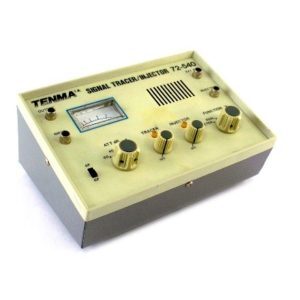
Some tracers combine signal generator and tracing capabilities in one box. The vintage Tenma 72-540 above is an example of this capability. It provides both audio and RF inputs and outputs.
DOCUMENTATION
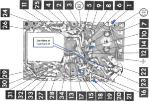
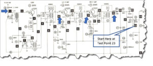
While not absolutely necessary a schematic, or better yet factory or Sams service documentation will make tracing much easier. For example, Photofacts show corresponding, numbered test points on both their schematics and circuit board photos.
So in the case of this Channel Master 6506 the center point of the volume control is labeled as Test Point 23 on both the schematic and circuit board photo.
Where to Begin
For this example, let's assume that you are starting with a completely dead Channel Master 6506 radio. If you are working on any mid-century transistor radio, there is a very good chance that one of these Quick Fixes can get it playing again. Try them before signal tracing or, heaven forbid, before attempting to align a radio.
- Connect the radio to a regulated bench power supply that you have set to the proper voltage and polarity, or load it with fresh batteries.
- Put your ear as close to the radio's speaker as you can. Switch the radio on. Do you hear a click or pop from the speaker? If you don't hear even a quiet click from the radio's speaker when you switch the radio on, use a voltmeter to confirm that power is getting into the board. Bad battery contacts, broken battery or speaker wires, broken PCB traces and faulty power switches are all common problems that will stop you dead in your tracks.
- If you are using a bench supply with an Ammeter, see if the current being drawn is within the range stated by the service documentation. For instance, Sams says that the Channel Master 6506 used in this example should draw between 4 and 5.5 milliamps.
- Next, connect the signal tracer 's ground lead to the radio's ground. In the Channel Master 6506 that's the battery's positive (+) lead. You can easily determine ground points from schematics.
- Set the signal tracer to audio input and, if the tracer has a volume control, set it about mid-way.
- Place the input probe on the center contact of the radio's volume control (Test Point 23). Listen to the tracer's speaker for signals. Adjust the tracer's volume control if necessary.
- With any luck you should hear atmospheric static, and hopefully, a local radio station when you tune one in. If you hear a local station, this means the antenna, tuning circuitry, mixer/oscillator, IF amplifiers and detector are all working. You won't know at this point if those stages are functioning optimally, but the set is able to tune in, amplify and receive broadcasts. This also tells you that you have a problem in the audio stage(s). The usual suspects are dirty volume controls, electrolytic capacitors, damaged traces, out-of-spec resistors and faulty transistors, transformers, or speaker, more-or-less in that order.
- Once you have solved the audio problem, determine if the overall performance is acceptable. Is the audio loud and undistorted? Can you receive stations at both the high and low ends of the broadcast band? Is the dial pointer reasonably accurate? If so, you are done.
- Otherwise, re-trace the signals listening for increases in the signal levels from stage-to-stage. When you suspect a faulty stage, compare its measurements with those listed in the service docs to further isolate the problem.
- As a last resort you can try aligning and/or recalibrating the radio.
If You Can't Hear a Local Station
When you can't hear a station by poking anywhere in the set while tracing you should suspect the antenna wiring, tuning circuitry, and perhaps the oscillator/mixer circuit.
If you have access to a signal generator, or injector and you inject a modulated IF signal (typically 455KHz, but sometimes 256KHz into the first IF section, and hear that tone in the radio's speaker, the fault is almost certainly in the tuning or Oscillator/Mixer sections.
Signal Tracing and Injecting Tips
- Practice signal tracing on a known-good radio to get yourself and the test gear calibrated. It's a good way to learn what traver settings to use and what a normal set sounds like when traced.
- Old PCBs had protective coatings on them that sometimes prevent test probes from making proper electrical contact. Use probes with pinpoint tips, or fashion one out of a thumbtack. Press firmly.
- If you hear rushing static sounds when you turn on a radio, and can control the noise with the volume control, the audio section is probably fine. Move on to the IF and other sections "to the left" on the schematic. If those stages are fine, narrow your search to the tuner and oscillator/mixer circuits.
- If you don't have a signal injector, and are working on a battery-powered radio, you can use your finger to inject noise into the antenna (Test Point 1 in the 6506), IF and detector inputs. Your body acts as a crude antenna and you will likely hear a slight buzz or other noise that your finger injects at these Test Points if the set is operational. The audio input might only produce a clicking sound on some sets.
- When injecting RF signals, use the lowest possible signal level. If the signal is too strong it can "leak" through a bad RF stage and will still be heard.
- When injecting RF it is very helpful to use modulated RF. That is to say, you need a signal source that sends an audio tone on the RF. Vintage signal generators nearly all did this. Many newer signal generators (a.k.a function generators) do not. The FY6900 is an exception. It can produce modulated RF signals.
What Do You Think?
Do you have tips and experiences to share? Questions? Suggested corrections or additions? Leave a comment below. I’ll review comments and post or incorporate the most useful ones. Your email address is required if you choose to comment, but it will not be shared.
I recommend you get “Transistor Radio Servicing made easy” by Wayne Lemoms. Download it at worldradiohistory.com. Easy why I found it was to google the title and then find the link to worldradiohistory.com and click on it.
Thanks Brian. Worldradiohistory.com is an amazing and incredibly-useful site. And Wayne is one of my favorite tech writers of all time.