Are You Sure?
The process described here is almost never a cure-all for a dead or weak radio. In fact, unless someone has badly adjusted the various RF and IF-related screws in a radio, or replaced transistors in the oscillator/mixer or IF sections, (described later), alignment is probably never the cause of a completely silent or very weak playing radio.
Dried up electrolytic capacitors, dirty volume controls, dirty/corroded battery contacts, defective/dirty earphone jacks, defective solder joints, disconnected wires, broken traces on circuit boards and battery corrosion on traces are far more common causes of dead or quiet vintage electronics than misalignment.
Tweaking the various RF and IF adjustments should be the last step in the repair process, and should only be done when you have confirmed that the radio is electrically functional. And tweaking means just that. It is rare to need to move a coil slug or capacitor trim adjustment more than a full turn. Quarter and eighth turns are more common.
If a set is playing acceptably you should probably not adjust it, especially if the set is valuable and you are inexperienced or lack reliable test equipment. It is possible to turn a beautifully playing radio into a paperweight, at least temporarily, by randomly fiddling with, or worse yet "tightening all the little screws in there."
When to Leave Things Alone
- If a vintage set plays well, gets a variety of strong and weak stations across the entire AM band with the dial indicating reasonably accurate frequency settings, I would leave it alone.
- If a radio is completely dead, I would look for electrical problems first. Instead of playing with alignment use signal tracing, voltage and current measurement techniques to rule out other, more common causes of silence.
- If you are rushed or tired take a break. Adjustments require patience and attention to detail. Set the project aside for a better day.
- These instructions will not work on non-superhet radios such as the two-transistor Boy's radios, the early Allied Knight two-transistor set, and most other "earphone only" regenerative radios or crystal sets.
- Do not use these techniques by themselves on FM radios, and especially not on FM stereo radios!
- These instructions do not tell you everything you need know to align multi-band shortwave, Marine band, and similar sets.
Hard-learned Advice:
In extreme cases you can damage parts and permanently injure valuable radios by misusing these instructions.
Practice First
Please do not start by prying open your favorite Regency TR-1 or Sony TR63. Start with something common, affordable and easy to toss if you really screw it up.
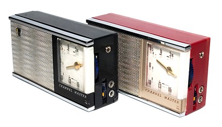
Channel Master 6506 (a/k/a RCA Victor P-332) sets are ideal for this. They are readily available, rugged, and big enough to be easily repaired. Since we use a 6506 in the Signal Tracing and electrolytic recapping sections here, see if you can find one and follow along.
What We Adjust and Why
Superheterodyne circuits were invented E. H. Armstrong in about 1928 and quickly became popular with engineers and consumers alike because of the performance improvements the designs provide.
At the risk of oversimplification, a superhet converts whatever incoming radio signal you have selected, 1400 KHz, let's say, to an intermediate frequency.
KHz and Kc are equivalent terms, "Kilohertz" (KHz) is the contemporary term. Kilocycles, (Kc) is an earlier term. Many vintage radios and schematics are marked in kilocycles, megacycles, and so on.
In AM sets the most common intermediate or "IF" frequency is 455 KHz. Some sets, (notably many early Regency pocket radios and car radios), use 262 KHz as their intermediate frequency.
So, in a typical Sony TR-610 pocket radio when you dial in your favorite station at 1400 on the AM dial the 1400 KHz RF signal gets converted to 455 KHz inside the set, and then this 455 Khz signal is strengthened, (amplified) before being converted to audio and delivered to the speaker.
This 1400 KHz to 455 KHz conversion is done because it's easier to design circuitry that will amplify a single frequency, (455 KHz, for example) than it is to design a broadband amplifier covering a wide range of frequencies, (550-1600 KHZ, or whatever).
When you adjust the three little cans in most superhets what you are doing is peaking their ability to amplify the IF frequency--455 KHz in most cases.
Suggested Sequence
- As with all things technical there are disagreements as to the correct order of steps. In general I think this is the best way to proceed, but read this whole document first. (You'll learn the specific how-to stuff in a moment with these steps fleshed out, I promise.)
- Tune the IF cans, beginning with the last and moving to the middle and then to the first IF stage.
- Tweak the Oscillator/Mixer coil.
- Tweak the Antenna Trimmer.
- Repeat as necessary.
If you have access to Sams Photofacts or factory service documents use the alignment steps and techniques described therein, especially if they disagree with these!
IF Tuning
When doing a complete alignment IF coils are usually the first things to be adjusted, and most techs start with the last IF coil (attached to the detector) and move closer and closer to the antenna. This process is sometimes repeated multiple times since the coils do interact with each other somewhat.
Tracking
A s you should know by now, superhets use "mixer/oscillator" circuits to do the conversion of the incoming signal to the IF frequency. Without getting into the details of this process it is important to mention that this conversion must happen uniformly over the range of the tuning dial, (550 to 1600 on most AM broadcast sets for example). Adjusting the tracking assures that your radio can receive across the entire frequency range it was designed to (550-1600, let's say), and that the dial pointer is reasonably accurate. Tracking adjustments are aimed at these goals.
Antenna Trimming
The final adjustment is made to the antenna trimming capacitor, a screw that helps "match" the antenna to the rest of the radio's "front end" circuitry. The better the match the better your radio will be at picking up weak signals.
A Typical RF/IF Circuit
Look at thee example of a typical RF/IF portion of a superhet radio below. In this instance it's a Channel Master 6506. Radio signals of all kinds bombard the antenna (L1) at the left of the schematic.
When you move the tuning knob one part of the dual or "ganged" tuning capacitor it's connected to, ( the left-most capacitor across the antenna coil with the dotted lines pointing to it), the capacitor tunes the antenna circuit to filter out all but the desired radio station's signal, (1400KHz, let's say). At the same time, another part of this dual section tuning capacitor adjusts the oscillator/converter circuitry down at L2. Follow the dashed line on the schematic to find it.
If all is well, the radio station's signal, (originally 1400 KHz) is presented to the first IF amplifier after having been "converted" to a frequency of 455 Khz. In the schematic the black box indicating test point 9 shows this point where the station's signal enters the IF section at 455 KHz. From here there are two stages of IF amplification provided by coil L3, transistor X2, coils L4, transistor X3 coil L5 and their related components.
The 1N60 diode at the right end of the schematic is the detector. It strips off the RF part of the signal and presents the audio to the volume control and audio amplifier, not shown in the illustration in order to save space. Some radios use transistors as detectors rather than diodes. Detectors are connected to the volume control, usually through a capacitor.

Adjustment Locations
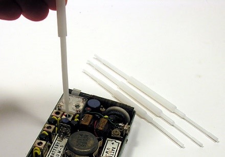
You will be making adjustments to the following: IF coils, an Oscillator/Mixer coil and one or two trimmer capacitors on the tuning capacitor. While they vary in size and appearance these are fairly easy to spot once you have opened a few radios and studied them.
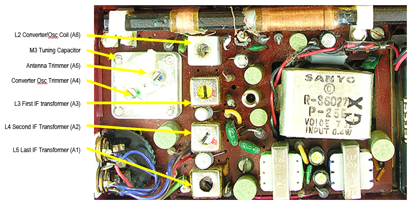
Look at this photo of a Channel Master 6506. The IF coils contain fragile powdered metal cores that are screwed in or out (up or down) to change the inductance of the coil.For this purpose, the slugs either have screwdriver slots or hexagonal holes designed to accept non-metallic alignment tools.
Bigger Sets, Bigger Parts
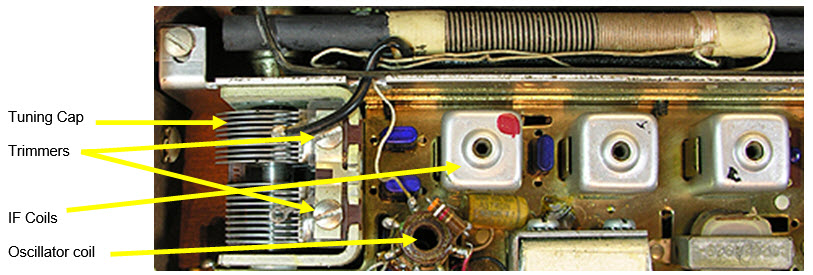
On big old sets like the Regency 8TP1 shown here the IF, Oscillator coils and tuning capacitor are larger. Notice the 'hex-shaped" holes in the IF coil slugs as opposed to the flat screwdriver slots in the Channel Master. The antenna trimmer and oscillator/converter trimmer screws are those big ones on the side of the tuning cap.
Signs of Damage
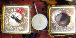
Notice the right-hand coil slug in the closeup. It does not have a clean slot like the one on the left. Part of the powdered core has been broken off by someone attempting to adjust the coil slug. The missing material will affect alignment and make it difficult to adjust. If you like radios that play, look for damage like this when shopping and be wary of sets that exhibit it.
Use Service Documents
Model-specific service documentation can be a lifesaver. In addition to factory documents, H.W. Sams published service documentation for thousands of radios. Both factory and Sams documents are available on eBay and Amazon.
Notice that Sams calls out the alignment points, conveniently numbered to reflect the recommended sequence of adjustments.
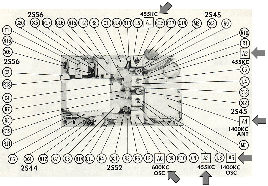
Manufacturers frequently published model-specific service documentation containing alignment instructions, and even schematics noting proper test voltages to expect along the way.
Nine times out of ten the steps and results will be identical or at least similar to those you will read here but there might be tips or quirks worth learning in those vintage pages, so check 'em out.
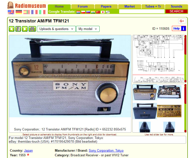
Another great source for these this is the Radio Museum website established in 2002. If you are a collector, you should both subscribe and contribute.
Using Test Equipment
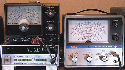 The best way to align a radio is to use an RF signal generator with a modulated output and an analog voltmeter connected to your radio's speaker terminals or earphone jack to monitor your progress; but as you will see later in this document you can survive without these luxuries. Until I moved on to more contemporary gear, here is a setup I used successfully. It's slight overkill, but this combination does speed things up.
With careful shopping on eBay, if you are patient, you should be able to get a similar setup for under $200.
As much as I love vintage tube test equipment, (Heathkit SG-8 generators, etc.); and did employ them for quite a while, I found myself spending nearly as much time fixing the test equipment as I did fixing broken radios, which was a problem here given the volume of radio repair work.
Used vintage solid state gear is a very workable, fun compromise. At a minimum, for AM radio alignments, you need an RF signal generator that can have its output modulated; which is to say the generator needs to be able to place an audio tone on the RF signal. Many newer digital "function generators" are often not capable of this, so shop for an RF signal generator with modulation. The small size and features of the B&K 2050 generator shown in the photo make it ideal; and they are fairly easy to find on eBay.
The frequency counter is overkill, but does speed things up, is reassuring, and keeps me from making dumb mistakes like improper range switch settings when using the signal generator.
You can monitor your alignment progress by listening to the speaker or an earphone plugged into the radio under test, but this is not as accurate as measuring the changes with a meter. (Family members take a dim view of the speaker method as well, and the earphone technique can further ruin your rock-music-damaged hearing). Use an analog meter.
Technology Marches On
I've sold all of that gear and now use the completely digital solution shown here. An FY6900 signal generator is at the center of the action. It two-channel design is capable of modulating its RF signals. Once you learn how, it's possible to save groups of settings and quickly recall them. So switching from 455KHz to 262 KHz or 1600KHz while aligning and then calibrating just takes a few button presses.
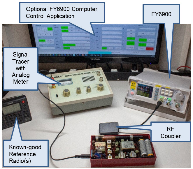
I sell complete FY6900 packages with the generator, RF coupler and step-by-step setup and use instructions HERE in my eBay store. Sometimes the generators sell out quickly, so you might need to check back, or drop me a note to reserve one. You can also purchase just the RF coupler and/or printed instructions in the store as well. A downloadable copy of the manual can be had right from HERE. It's titled AM RADIO ALIGNMENT Using the FY9600 - The Missing Manual.
Homebrew Aids
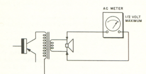 While you can attach a digital AC voltmeter to the radio's output and watch the numbers increase and decrease it's not as easy or accurate. Analog meters are better for this task. And besides, the coolness and ease of watching the needle rise and fall an analog meter has a bit of a Buck Rogers Zen to it. You will be measuring AC voltages under 1-volt. Incidentally, the bigger the meter face the easier it will be to see small improvements. Here's how to do it as described in the vintage book Transistor Radio Servicing Made Easy by Wayne Lemons.
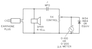 Alternately you can build a simple device that you can plug into the earphone jack using a circuit like this one. Consider adding a switch to the speaker or replace it with a 10-ohm resistor. Otherwise you will need to listen to noise as you work. The resistor places the necessary load on the set's output in place of the speaker.
Coupling the Signal
You want to get the weakest usable modulated RF signal from your signal generator into the set, and then adjust the coils and trimmer caps to improve the signal strength. Do this by either attaching a short coil wire, or better yet, a cable with a loopstick antenna wired to the output of your signal generator and then place this signal source in the proximity of the radio as shown above.
You want the signal to reach, but not over-power the radio. Newer signal generators require capacitance between the coupler coil and the generator's output to prevent shorting the generator.
Adjusting IF Coils
- Turn on your signal generator, enable the internal modulation tone and set the RF output frequency to the radio's IF frequency, (usually 455KHz). Let the generator warm up, preferably for 20 minutes or so. Fine tune the generator's frequency setting after the warm-up if using a frequency counter.
- Turn on the radio and set its tuning knob to the high end of the band where there is no station (1600, or wherever).
- Turn the radio volume up as high as you and the dog can stand it.
- With the generator's output level set very low listen for the tone. If you can't hear the tone, increase the generator's signal strength and/or move the signal source closer. If this still doesn't work substitute a known good radio and try again to confirm proper setup of your test equipment. If all else fails, rock the signal generator's frequency setting knob back and forth until you can hear the sig gen's tone on the radio being repaired.
- Once you hear the tone, connect an AC voltmeter, if you have one, to the speaker terminals or earphone jack.
- Confirm that the signal generator is at the correct IF frequency, (455KHz or whatever)
- Starting with the last IF coil (A1) adjust a little bit at a time watching and/or listening for an increase in the tone's volume. This will normally require less than a full turn of the tool. Stop when it peaks.
- Move to the "center" IF coil (A2) and tweak it as before.
- Move on to the coil closest to the "front end" or antenna section of the radio. (A3)
- Repeat Steps 7-9 once or twice more to see if you can squeeze out a little more signal.
Some Alignment Tips
- Always tune using a very weak signal. As the alignment improves reception and the signal from the radio gets stronger, lower the generator's output and/or move the signal source and radio farther apart. You don't want the radio's AVC or AGC circuitry to kick in as this will make it difficult or impossible to measure changes.
- If the radio starts squealing back off the adjustment a bit.
- Sometimes you will see/hear two "peaks" when tuning an IF coil. You want the stronger of the two.
Adjusting Tracking
With the IF alignment done you can move onto the radio's tracking. This ensures that you get all the stations in the band and that they appear in about the right places on the dial.
- Tune the radio and the signal generator to 600 or a nearby, station-free frequency.
- Alternately adjust the oscillator/mixer trimmer capacitor (A4), and the tuning dial until you get the optimal signal with the pointer pointing at or about 600. Look at the dial. Is it pointing at the right number? If not, move the trimming cap slightly and then move the tuning dial. Is it closer? If not move both in the opposite direction. Remember, this ain't NASA, the radio's probably 50 years-old, was mass produced, and the dial's gonna be approximately right, not perfect. Work back and forth until you grow bored with this.
- Set the signal generator to an empty space near the high end – 1500 or 1600 perhaps, and adjust the oscillator trimming capacitor but, if possible, not the coil, (A4) using the techniques described in step 2.
Note: If the peak occurs at one end of the capacitor trimmer's adjustment range or the other, return the trimmer to its center position and slightly adjust the oscillator/mixer coil for maximum signal strength first, and then repeat the trimmer cap tweak. Only fiddle with this coil adjustment if absolutely necessary.
- Tune both the radio and the signal generator to 1000 or a nearby, station-free area near the center of the dial.
- Adjust the antenna trimmer normally found on the tuning capacitor, (A5) for best strength.
Adjusting Without Test Equipment
You can do a remarkably good job of perking up an AM radio with nothing more than a fluorescent light or other noise-generating appliance and some non-metallic tools. When I first read about this in Wayne Lemons' book titled Transistor Radio Servicing Made Easy I was skeptical, but it works. Again, try this on a set you can afford to mess up for practice. Remember, MINOR adjustments usually do the trick.
- Bring the radio near enough to a fluorescent light to hear the hash sound generated by the light.
- Tune the last, middle and then the first if coil for maximum noise, moving the radio away from the source as the "white noise" loudness increases.
- Tune the radio to the low end of the band (600KHz).
- Adjust the oscillator/mixer trimmer cap on the tuning cap, (A4) for loudest noise. If the peak occurs at one end of the adjustment range or the other, return the trimmer to its center position and adjust the oscillator/mixer coil for maximum noise first, and then repeat the trimmer cap tweak. Only do this coil adjustment if absolutely necessary.
- Tune the radio to weak station at around 1400, or as near the high end as you can hear one.
- Adjust the antenna trimmer cap (A6) for maximum noise, or if there is a station up there you can maximize its loudness instead.
- Move to the low end of the dial and tweak again.
- Repeat the process a few times to optimize reception.
Alignment Tips and Techniques
Here are some tips I've collected over the years. BTW: I am always interested in hearing and sharing yours, so drop me a note at ronmansfielde@gmail.com.
Wax Plugs
The wax in many IF coils is there to keep the slugs from moving. Pry out the wax plugs covering IF coil slots with a dental pick or screw driver. Drip candle wax back into the holes when done. Candle wax is also a great way to cure "floppy" antenna coils by sticking them to the circuit board.
Is the Oscillator/Mixer Working?
A quick way to see if the oscillator/mixer stage is working is to bring the problem radio in proximity with a known good radio. Set both to quiet spots near the middle of the dial. Rock the tuning dial on the problem radio. If you hear a squeal in the good radio, chances are the oscillator/mixer is functioning, although not necessarily adjusted properly.
Metal Cases
Metal cases and even batteries can affect alignment. When possible, align radios in their cases with the battery in-place, even if you are using a bench power supply.
Tight Corners
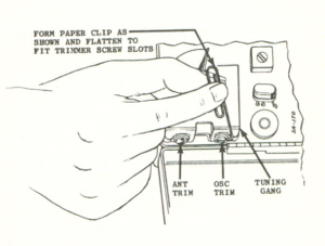 Here's another great tip from Leonard lane's How to Fix Transistor Radios and Printed Circuits, V2. To reach tightly-packed trimmer adjustments unfold a paperclip, flatten the extended end and use it as a screwdriver. Your body and the metal clip will have some effect, but it can still be a time saver:
Dealing with Broken Slugs
Broken IF and oscillator coil slugs are not the end of the world, but they will affect operation. Sometimes you can back them out of the coil and create a new slot then re-insert them. Try a very small drop of epoxy on a toothpick to create a handle used to unscrew broken slugs. Don't glue the slug to the core in the process! If you have a spare parts radio perhaps you can swap slugs of the same kind.
Other times you will need to remove the IF coil's metal can first in order to get the slug out since the slug is bigger than the hole. If you are going to this much effort, see if you can find a replacement IF can from a parts radio instead, and replace the whole part. Use care as these are pretty easy to damage with excessive heat.
Aligning 262 KHz IF Radios
Some popular collectibles with 262 KHz IF circuits include the Regency TR-1, TR1G and TR6. Many car radios used 262 as well.
What Do You Think?
Have you ever attempted an alignment? How did it go? What are your favorite alignment tips? Questions? Suggested corrections or additions? Leave a comment below. I’ll review comments and post or incorporate the most useful ones. Your email address is required if you choose to comment, but it will not be shared.
Thank you for your tips and advices ! Its like a Fast track of the alignment procedure, well explained and works great. Keep the good work going !
I learned 2 minor details that made a huge improvements on vacuum tubes radios .
Greetings…
Great walk through and greatly explained! Thanks for sharing!
~hadi
Another thing worth checking is to see if the antenna coil has loosened and shifted position on its ferrite rod/bar/whatever, presumably from being dropped. Or maybe not being secured during assembly. Had a unit that worked intermittently at the lower end of the dial, depending on its positioning or being shaken. If this problem is found, tune into a station (if possible) at the lower frequency part of the dial. Or use a signal generator, and with a plastic or wooden tool move the paper- or plastic-backed coil winding assembly along the ferrite field intensifying rod for best results (peak the signal). This can have a significant effect on reception as it affects the inductance and therefore the resonance of the antenna. Had this most baffling dominance of image-frequency reception on a set till I noticed the ridiculous mobility of the coil winding. Secured it into place with some silicon seal. Be careful to just use a tiny dab at the end of the coil backing, to the rod. It doesn’t take much. The material could affect the insulation, and I read, the induction of the coil. Let it set overnight and you’re good to go
p.s. Don’t fool with this unless you find the coil really is loose, as there shouldn’t normally be any need. You don’t want to waste time and/or cause damage as that is the job of the farm animals who break these things.
Great tips! Thanks. Another way to secure antenna coils is with a drop or two of candle wax. Also, dropped radios sometimes have cracked/broken antenna rods. Another cause of poor reception.
Nice procedures! If you haven’t done it yet, Review the utube videos of am or vintage radio alignment. you can see real restoration especially after capacitor replacement or tubes replaced. Nice work. Bob KD8VFC