Electron Flow
Electricity is a flow of electrons from one place to another through things. Electrons always want to return to their source if they can, making something called a complete circuit.

Direct Current (DC)
Consider the lowly flashlight, for example. Electrons flow from the negative terminal of the battery or batteries, through the switch, into and then out of the bulb, and back to the positive battery terminal.
In the process, the resistance created by the bulb (or LED these days) frustrates the electron flow creating heat and light.
When the flashlight switch is open (off) the electrical path is interrupted, and electrons cannot flow through this incomplete circuit. Closing the switch completes the circuit, and electrons flow.
In Direct Current (DC) circuits current always flows in the same direction, which is from Negative to Positive.
Oddly, in very early electronics books we are taught that electrons flow from Positive to Negative. That's not the case.
Alternating Current (AC)
If only things were always that simple. In Alternating Current circuits electrons flow first in one direction, and then in the other.
The number of times the direction changes is called the frequency. For our purposes this is measured in cycles-per-second, (CPS), thousands of cycles-per-second (KC), and so on. These measurements are also referred to as Hertz (Hz), Kilohertz (KHz), etc.
SparkFun has a really good tutorial on AC and DC.
The Concept of Ground

Another helpful thing to know about radio design is grounding. Brits also refer to this as earthing. The concept originated when electricity was in its infancy.
A related concept is common, or return paths within electronic and electrical devices. Let’s look at both.
Why Ground?
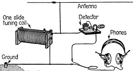
Grounding provides a return path for electrons which always want a to go back to their origin. Early radios needed grounding to improve their reception. This was primarily because circuitry and antenna designs were not sensitive enough to properly pick up radio signals back then.In the literal sense grounding connects electrical devices to the earth itself.
A long metal stake was (is) driven into the soil and devices are attached to it using hefty wire.
Your house electrical system is connected to a grounding rod or to a buried pipe somewhere, typically near the circuit breaker box. Lightning rods connect to the earth this way as well.

Grounding early radios improved reception, but made listening to them while carrying them around all but impossible. As designs improved it became less necessary to ground radios.
But there is another type of grounding to be understood. Even though most contemporary radios needn’t be connected to the earth, they all have their own ground systems within them. These are called common grounds or return systems.
Here's some great information about grounded crystal sets from the fantastic site Wikiwand.
Common Return Paths
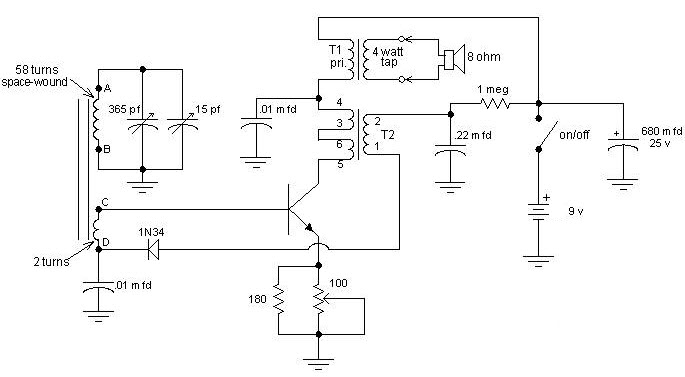
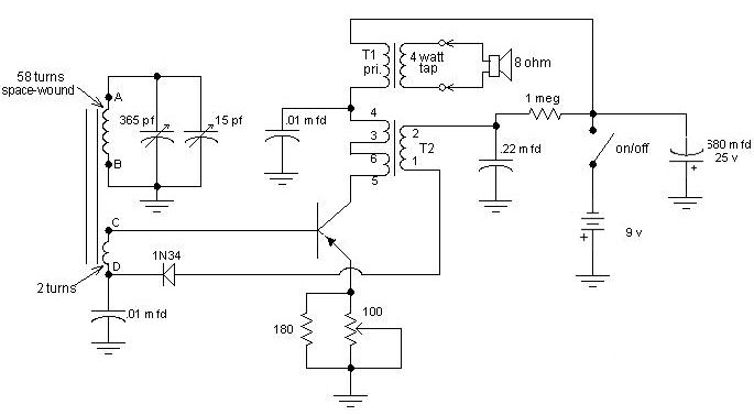
Portable sets are said to have either Negative or Positive common grounding. This tells us which battery pole is connected to the common ground. Look at the differences in these two schematics. Can you tell which is a negative ground design, and which is the positive?


Right. The top schematic is a negative ground design. The bottom set has a positive ground configuration.
In a negative ground set the minus poles of batteries and electrolytic capacitors connect to the (common) ground. NPN transistors are typically used.
Positive ground systems reverse battery and electrolytic polarities with respect to ground, and typically use PNP transistors.
What Do You Think?
Do you have tips and experiences to share? Questions? Suggested corrections or additions? Leave a comment below. I’ll review comments and post or incorporate the most useful ones. Your email address is required if you choose to comment, but it will not be shared.
Be the first to comment